AC-AC Converter - Building Block in Solid State Transformer


This article discusses the role of isolated AC-AC converters from the perspective of solid-state transformer technology. It explores various topologies, shedding light on the advancements in high-frequency link AC-AC converters for efficient power distribution.
The fundamental component of solid-state transformers is the isolated AC-AC converter with a high-frequency connection. A conventional converter has a higher number of switches, which increases the size, cost, and complexity of the system. However, with modifications in the circuit, it can be improved.
Isolated AC-AC converter
The topology depicted in Fig. 1 can be used to explain the working concept of the isolated AC-AC converter.

Fig. 1 Phase-controlled AC-AC converter with high-frequency link. Source: IEEE Access
The four-quadrant switches S1 and S2 divide the AC input voltage Vin to create a high-frequency amplitude-modulated voltage that is applied to the high-frequency transformer.
The four-quadrant switches S3 and S4 rebuild a low-frequency sinusoidal voltage Vout at the output terminals, change its phase, and make it match the sinusoidal voltage that comes in.
Despite being straightforward, this design has limited applications
- Difficult to commute
- Low efficiency
- Exposes semiconductors to sudden voltages that are at least twice as high as the input voltage peak
However, soft switching of the converter switches is needed to achieve better efficiency and a reduction in electromagnetic interference.
AC-AC Converter Using the Series-Resonant LLC Converter
As the idea developed and semiconductor technology advanced, the design called the AC-AC converter using the series-resonant LLC converter depicted in Fig. 2 was developed. The topology comprises
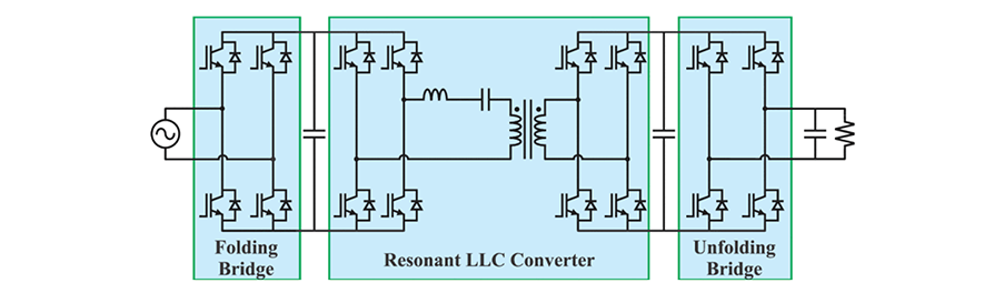
Fig. 2: AC-AC converter using the series resonant LLC converter as a high-frequency link Source: IEEE Access
Folding Bridge
In this architecture, a folding bridge rectifies an input voltage of 60 Hz sinusoidal to produce a rectified 120 Hz sinusoidal voltage.
Resonant LLC Converter
An LLC resonant converter makes up the second stage. It operates at the resonant frequency, which guarantees the switches to commute softly. Furthermore, the transformer turn ratio alone determines the voltage static gain at this frequency.
Unfolding Bridge
The final stage is an unfolding bridge, which generates a sinusoidal voltage in the load that is a mirror image of the sinusoidal input voltage. It operates at a frequency of 60 Hz and is synced with the sinusoidal input supply voltage.
The increased number of semiconductors is one difficulty in this topology. Several different topologies use the LLC converter to convert AC-AC energy, each with pros and cons of their own.
AC-AC Converter with High-Frequency Isolation
The set made up of the unfolding bridge and the LLC resonant converter's output rectifier was replaced with a stage made up of four-quadrant switches to minimize the number of semiconductors.
The topology under study, depicted in Fig. 3, can be understood as a hybrid of the converters depicted in Fig. 1 and Fig. 2.
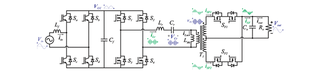
Fig. 3: AC-AC converter with high-frequency isolation using the LLC series resonant converter. Source: IEEE Access
An extensive examination of the converter is provided in this article, all aimed at confirming its functionality and suitability as a solid-state transformer’s building block.
Fig. 3 depicts the two-stage AC-AC converter with high-frequency isolation that uses the LLC series resonant converter and is made of two stages.
- Folding bridge
- LLC Resonants Series Converter
Folding Bridge
It is composed of the
- Power semiconductors Sa, Sb, Sc, and Sd
- Inductor Lf
- Capacitor Cf
The first stage is a folding bridge that transforms a sinusoidal voltage of 60 Hz at the input into a sinusoidal voltage rectified at its output at a frequency of 120 Hz.
The Lf and Cf filter's sole purpose is to filter high-frequency voltages and currents; they do not affect the fundamental voltage waveform's value or shape.
This stage uses controlled devices rather than diodes. It permits the circulation of reactive power generated by high-frequency input and output filters or non-resistive loads.
LLC Resonant Series Converter
The second stage is made up of an LLC resonant series converter working at the resonance frequency, which comprises
- Output stage
- Resonant inductor, Lr
- Resonant capacitor, Cr
- Switches S1, S2, S3, and S4
- High-frequency isolation transformer. T1
The average, effective, and maximum current and voltage values of the power semiconductors must be determined in order to choose them correctly. The power stage components that can sustain these stress values and enable the proper functioning of the converter must be chosen.
Due to the numerous variables and parameter selections, the transformer of an LLC converter, which is utilized in converters with variable switching frequencies, must be designed with precision.
Principles of Operation
A traditional LLC resonant converter's output stage produces a voltage that is exclusively positive polarity and employs unidirectional switches. To achieve the sinusoidal voltage at the load, a second stage that operates in synchrony with the input voltage must be used.
The bidirectional switches in the suggested converter have taken the place of the unidirectional ones. When bidirectional switches are operated correctly, they can produce an output voltage with both positive and negative polarities, eliminating the need for a second stage to reconstruct the low-frequency sinusoidal output voltage.
Four steps comprise the operation of the high-frequency stage of the ideal component converter: two phases take place during the positive half-cycle and two phases during the negative half-cycle of the sinusoidal input voltage.
Thus, the high-frequency stage switches are controlled so that the voltage in the load is always positive during the positive half-cycle of the alternating input voltage. They are adjusted to produce a negative voltage during the input voltage's negative half-cycle.
The voltage static gain of the LLC resonant series converter depends only on the transformer turn ratio because it operates close to the resonance frequency.
Without the necessity for closed-loop control, an output voltage that is an image of the input voltage is obtained. Fig. 4 displays the sinusoidal voltage and current at the converter's output terminals.

Fig. 4 Waveforms of the sinusoidal output voltage and the output current Source: IEEE Access
The output capacitor Co is chosen to absorb the harmonics of the high-frequency current. It needs to have the lowest capacitance feasible to prevent the converter from circulating reactive power that isn't needed.
To conclude, a high-frequency link AC-AC converter that used a resonant LLC converter that operated close to the resonant frequency was examined. Unlike the usual method that employs two power conversion stages, the architecture uses a single output stage made up of four quadrant switches.
The architecture under study is appropriate for use as a solid-state transformer building block for medium-voltage power distribution.
Summarizing the Key Points
- Isolated AC-AC converters are fundamental components of solid-state transformers
- AC-AC converters using series-resonant LLC converters improve efficiency and reduce electromagnetic interference
- The folding bridge in the AC-AC converter transforms a sinusoidal voltage of 60 Hz into a rectified 120 Hz sinusoidal voltage
- The LLC resonant converter operates at the resonant frequency, ensuring soft switching of the switches
- LLC resonant series converter is appropriate for use as a solid-state transformer building block for medium-voltage power distribution
Reference
Pacheco, Leonardo F., Kaio C. M. Nascimento, and Ivo Barbi. “Isolated AC/AC Converter With LLC Resonant Converter High-Frequency Link and Four-Quadrant Switches in the Output Stage.” IEEE Access 8 (2020): 213104–14. https://doi.org/10.1109/access.2020.3040617