What is Low Pass Filter
When working with electrical parts and electronic signals, it is important to consider both time and frequency domains. The time-domain reflects the voltage value of the signal at a specific time. While frequency domain represents information about the various frequency components that form the signal, which is also known as “Spectrum”.
In real-life, almost all signals come with noise that affects signal shape in the time domain and change the voltage values. These noises are caused by frequency components that may be either low frequency or high-frequency components. And the most efficient way to get rid of the noise is to use “Filters”.
Filters are electronic circuits that prevent a specific range of frequencies from passing into the system. In other words, it removes the unwanted frequency components from the spectrum to reduce the noise or increase efficiency.
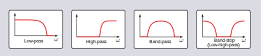
There are different types of filters depending on their characteristics and frequency response. The main four types are; Low-Pass Filter, High-Pass Filter, Band-Pass Filter, Band-Stop Filter. In this article, we will discuss the low pass filter and its specifications.
Low-Pass Filters
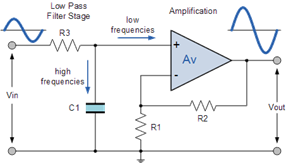
As the name means, low-pass filters are circuits that passing only low-frequency signals and try to block the passage of high-frequency signals. We can separate low and high ranges by a specific threshold as the system needs, and this threshold is achievable by adjusting the values of filter components. Low-pass filters may be passive or active. The passive filter means it uses resistors, capacitors, and inductors. While the amplitude of the signal is the same or lower than the original. On the other hand, active filters can both filtering and amplifying the signal as they may have transistors or operational amplifiers.
Passive Low-Pass Filter
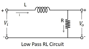
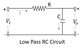
There are two basic kinds of circuits capable of achieving low-frequency filtering, and many variations of each one, the inductive low-pass filter (RL), and the capacitive low-pass filter (RC).
RL Filters consists of an inductor and a resistor connected with the load in series. Relying on inductor specifications, its impedance increases with the increase of frequency. Therefore, the high frequency will cause a high impedance which will block the signal from reaching the load. In conclusion, the amplitude of high-frequency components will be very low and have almost no effect on the full signal. The following figure shows the amplitude depending on the frequency.
On the other hand, RC filters are built using a resistor and a capacitor connected in parallel with the load. High-frequency signals will decrease the impedance of the capacitor, allowing most of the voltage to drop across the capacitor. Similarly, low-frequency signals will pass through the load as the capacitor impedance will be much higher than the load's resistance.
Cut-Off Frequency
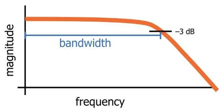
When analyzing the frequency response of the RC filter, we can recognize to main areas. "Passband" is the range where the filter doesn't affect the frequency. While "StopBand" is where a significant attenuation appears on the frequency range. The transition between those two areas is always happening gradually. As result, there is no specific frequency where the filter will stop passing the signal. However, to identify the response of a filter we need to define a point where we can consider that the filter had started blocking the frequencies. This led to the "Cut-Off Frequency" concept.
Engineers found that the ideal cut-off frequency in RC filters could be the frequency where the output power reaches 50% of its original value. This is equal to 3db reduction, which means that the cut-off frequency is the -3db frequency. This value also refers to the bandwidth of the filter.
Other interesting articles to read: "Understanding the T Flip-Flop" and "An Introduction to Ground: Earth Ground, Analogue & Digital Ground"