Understanding the T Flip-Flop

Digital circuits are the basic building blocks for most computing devices. Digital circuits are divided into two main types: Combinational Logic Circuits, and Sequential Logic Circuits.
What’s the difference?
In combinational logic circuits, logic gates form the basic component of a circuit, which means that the output of the circuit at any time relies only on its inputs at that time. On the other hand, in sequential logic circuits, the current state of the system depends on both the current inputs and the last output, and the main unit of these circuits is "Flip-Flop".
Flip-Flops & Latches
A Flip-Flop is a digital logic circuit that mainly forms 1-bit data storage. It is also a bistable multivibrator as it has two stable states "0" or "1". Developers can usually form a Flip-Flop by combining NAND and NOR circuits with a clocking source or, simply get a pre-built Flip-Flop on ICs from an electronics store locally or from an online electronic components distributor. "Latches" are similar components to Flip-Flops but the main difference is their clocking mechanism. Flip-Flops are controlled by a clock source and the inputs only affect the clock edge. While in latches, any change in inputs affects the output immediately. Flip-Flops tend to have many different applications such as building counters, shift registers, frequency dividers, and more.
However, there are four main types of Flip-Flops:
- SR Flip-Flop
- JK Flip-Flop
- D Flip-Flop
- T Flip-Flop, we will expand on this topic below.
The T Flip-Flop
T Flip-Flop is a single input logic circuit that holds or toggles its output according to the input state. Toggling means changing the next state output to complement the current state. T is an abbreviation for Toggle. A good example to explain this concept is using a light switch. When you toggle a light switch you are either changing from the on state to an off state and vice versa. Check out switch toggle e.g. 26ET61T and switch rocker like the AML24EBA2AA01 electronic part here.
The main purpose of T Flip-Flop is to avoid the occurrence of the intermediate state in SR Flip-Flop.
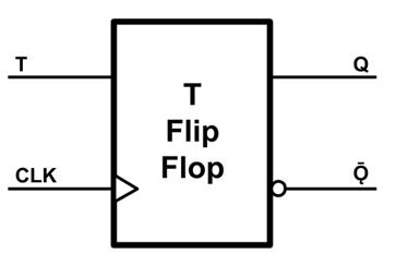
The following figure shows the logic symbol of the T flip–flop. It has one Toggle input (T) & one clock signal input (CLK).
You can build a T Flip-Flop from the other types of Flip-Flops, or by using logic gates as indicated by the below methods:
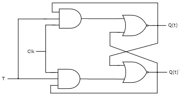
1) Using 2 AND, 2 NOR Gates
In this application, we need two AND gates connected to two NOR gates. Each AND gate needs 3 wires; a common toggle input (T), a common clock signal (CLK), and a feedback wire from the present state output (Q) or its complement (Q'). Then connect these AND gates as inputs for the NOR gates with a wire from the other NOR gate output. The following figure represents this method:
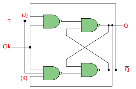
2) Using 4 NAND Gates
This method uses 4 NAND gates and is similar to the method described above. Two gates will be connected to the inputs and two with the outputs. Each input gate also has three input wires; toggle input (T), a common clock signal (CLK), and a cross feedback wire from the state output. Those gates form the input for the other ones with cross feedback from the output as shown in the figure:
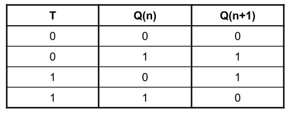
T Flip-Flop could be a positive or negative edge-triggered device. In other words, the inputs will affect the output only when the clock signal changes from low to high for positive, or from high to low for negative. However, when an edge applied to the clock input, the Flip-Flop will hold or latch the last output (Q) if T=0, and will toggle it to its complement if T=1.
Below you can find the truth table for T Flip-Flop:
We can find T Flip-Flop in many applications, mainly in frequency dividers, binary counters, and parallel load registers.
To build a frequency divider you will need two T Flip-Flop electronic parts. Connect their toggle inputs to high "1", then connect the output of the first Flip-Flop as a clock for the other one. The final output will be half the frequency of the main clock, and those outputs can be used also as binary counter bits.
If you need to use the T Flip-Flop in your circuit you may not find an IC that implements it, but you can use a JK Flip-Flop IC (i.e., 74107 or 7476) and short both J and K inputs together to make it a single T input.
Conclusion
This article provides a brief overview of the Toggle Flip flop family. We are always keen on feedback on how some of these concepts are applied in the real world of electrical engineering, so throw us some comments for discussion.